[later note: this is the wrong Xbee to use; should be "series 1" marked S1, = a plain 802.15.4.]
Connected via USB mini on a Gravitech adapter board.
1st step: Download X-TCU program from maker digi.com
2nd step: Install FTDI drivers for VCP (virtual comm port)

After a few seconds it discovers the device and shows up as a box in list with Port definitions and MAC address.
I was planning to start directly with two arduinos and two Xbees. However, there is a built-in terminal to allow direct communication. I proceeded using it. The manual shows communication check with adjacent windows from two separate computers. I duplicated the setup on a 2nd PC.
Select the Terminal tab; define a packet by clicking "+" and then typing some text. I switched from ASCII to HEX tabs and added 0A to include a linefeed. No results.
Further reading says to set addresses for MY and DL. If all at DL = 0, should work, but doesn't. Says MY must be set as well, but it is Read-Only. Only reference to this is a blog post saying MY is read-only for XBee 2, but not 1.
To verify PC-to-Xbee connection, the AT command +++ can be typed; it should respond with OK.
++++OK
This did work. (Seems you have to touch the Baud rate function first in some cases.)
Couldn't make additional progress beyond this step. Decided to contact Digi. Have to register in order to send a tech question.
-- tech support helpful. Turns out there are several flavors of the modules. The units I started with are not the right choice for a direct connect, nor are directly compatible; in the lingo, there are Series 2 and original (now called Series 1). The Series 2 are more suited more mesh networks and have much lower effective data rates. I was able to configure by setting one xcvr as "coordinator" and is sufficient to send some data.
I ordered a pair of the right ones XBP24-ASI-001 (decoded means XBee Pro @ 2.4GHz Series1/802.15.4, version with SMA antenna connector).
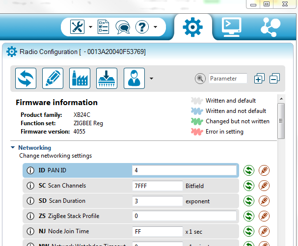
Necessary steps with software are still to set to matching PAN ID. It is optional but not necessary to set the MY and DL values to complementary values on the pair. If both are 0, every device gets everything. Else, suggested values are 10, 11 and 11, 10 respectively. No mention of range of other value pairs. I left values at zero.
After seeing transmitted and received messages show on the respective terminal screens (yea!), I proceeded to set up a repeated message, possible in the terminal. I carried the laptop and xbee through the building to confirm that it maintained communication at 50-100 feet through a couple of walls. Good.
The data stopped appearing in the terminal window after a few minutes. Tried clearing the window with the provided button (but it didn't), and eventually found that disconnecting xbee USB and restarting XCTU were necessary (but not always sufficient) to re-establish connection.
Long story short is that there are limitations with terminal window: after 4000 characters are sent (~2-3 minutes at 500ms repeats), it stops updating in text display window, though communication and data transfer are actually still functioning. Also, a bug in the program was revealed: the Clear Buffer button only works if the received data is less than its maximum. Once it's full, the button no longer works. I found no way to recover from this. But once I knew, all was well.
One other problem appeared soon after; some glitch occurred when I read back data from XBee, and nearly all values are scrambled and appear red. Couldn't clear by re-writing defaults. Resolution was the usual de-power the board, and restart everything. Problem did not re-appear.

The suggested troubleshooting choices did not apply in my case. It is caused by having the Rx,Tx connected to microcontroller when the Add or Discover Radio module is pressed. I had to physically disconnect serial lines (Rx,Tx) in order for XCTU to find it. Needless to say, this is easy to forget about if you close and relaunch. I do not know why this would be necessary.
Suitable arduino software based on echoBoth.ino receives and re-transmits text from either end.
1st arduino code:
---
/* UART Example, any character received on either the UART (HW serial)
 or USB serial is printed as a message to both ports.
*/

#define RF_SERIAL   Serial1       // UART
int led_pin = 13; // on-board LED
int t0 = 999;   // ON period (1/frequency)
int d1 =  60;   // ON duration

void setup() {
  pinMode(led_pin, OUTPUT);
  while (!Serial && (millis() < 8000)) {  // program continues if the monitor window is never opened
    ; // wait for serial port to connect. Needed for Leonardo & Teensyduino 3
  }
  Serial.begin(9600);
  RF_SERIAL.begin(9600);
}

void loop() {
  char inB;
  char inC;
  if (Serial.available() > 0) {
    digitalWrite(led_pin, HIGH);   // LED on
    inB = Serial.read();
    Serial.print("USB:    ");
    if (inB < 48) Serial.print(' ');
    else Serial.print(inB);
    Serial.print("   ");
    Serial.println(inB, DEC); // print numerical value of ascii char

    RF_SERIAL.print("USB: ");
    if (inB < 48) RF_SERIAL.print(' ');
    else RF_SERIAL.print(inB);
    RF_SERIAL.print("   ");
    RF_SERIAL.println(inB, DEC);
    digitalWrite(led_pin, LOW);   // turn the LED off
  }
  if (RF_SERIAL.available() > 0) {
    inC = RF_SERIAL.read();
    Serial.print(millis() * 10 / 10000.0);  // print a time-varying value to see consistent output
    Serial.print("   ");
    if (inC < 48) Serial.print(' ');  // print space for characters below printables
    else Serial.print(inC);
    Serial.print("   ");
    Serial.println(inC, DEC);

    RF_SERIAL.print(millis() * 10 / 10000.0);
    RF_SERIAL.print("   ");
    if (inC < 48) RF_SERIAL.print(' ');
    else RF_SERIAL.print(inC);
    RF_SERIAL.print("   ");
    RF_SERIAL.println(inC, DEC);
  }

  // blink light and print a msg at a fixed interval in addition to other inputs
  if (millis() % t0 == d1) {
    digitalWrite(led_pin, HIGH);   //
    Serial.println(millis());    RF_SERIAL.println(millis());

    delay(1);       // skip 'til next tick
    digitalWrite(led_pin, LOW);    // turn the LED off
  }
}
---